Draw to Print
Web-based modeling tool for 3D-printing
The existing paradigm for modeling to printing relies on the 3D modeling eco-system established so far. However, The general slicing programs also mitigate the potential of printing. Meanwhile the widely used digital modeling method is not friendly to the intuitive arbitrary creation. These two factors prevent creators from a more intuitive creation experience. Thus we aim to create a tool that provides an intuitive, hassle-free creation experience, enabling arbitrarily creating the path in 3D space to printing.
Collaborator: Zhishen Chen
Instructor: Jose Luis Garcia del Castillo Lopez
April - May 2023

Design Problems
- Printing Process

The 3D printing process that we are familiar with has a working diagram that goes through mesh modeling, a slicer process, and finally G-code printing.


The slicer process is an interval in this diagram that interpret the modeling data into printable data. Meanwhile, it makes the inner logic of printing differ from the original modeling logic when we create the object.
This is also reflected in our CAD tools in modeling and printing. Slicer tools are used after general modeling software to transfer digital modeling into a printable object. It is a dissociated process in an integrated design workflow.


More concrete problems of the slicer process can be seen when we want to print a single-layer non-planar PLA object or any arbitrary pattern which are not widely supported.
The existing paradigm for modeling to printing relies on the 3D modeling eco-system established so far. The standard process enables a wider range of applications but also imposes quite constraints on the final products.
Can We Model The Printing Path Directly?
Imagine a tool that connects and interprets arbitrary modeling to 3D printing through an intuitive and hassle-free approach.
- Drawing & Modeling Process
Respectively, the traditional modeling process is not well aligned with the principle of 3D printing (additive manufacturing) —— print path in space. The general slicing programs also mitigate the potential of printing. That leads to the core, the more general problem for many modeling software today: how to let the user create a line/curve in 3D space through the 2D interface?

Drawing a 2D line on the canvas in the real or digital world is never a big deal. However, when the dimension of the drawing experience is increased to 3D, things get different.

Drawing a 3D line in real space, even like the VR drawing experience, is reliable since people have real cognition of 3D space when they draw the line.

However, when drawing a line on the computer(on the web or a 3D modeling tool), which means we are drawing a 3D line with 2D perspective in an unreal 3D space that was simulated on a 2D screen, people can not easily or arbitrarily draw a 3D line since the real cognition of space was impaired or lost.

In traditional 3D modeling tools, creating a 3D line typically involves drawing the line by clicking and dragging the cursor in the desired direction in a 2D perspective. The user can then adjust the vertices' position and other properties to make the line go in the right way. But it could be inefficient if we want to create something fluent, arbitrary, and irregular.
Though drawing (drafting) is one of the most intuitive creation method of creator, because of the limited cognition of the depth of the 3D space in a simulated 2D screen, the arbitrary drawing(creation) process has to be broke down into two parts: draw and adjust. Therefore before the problems of printing, we have the problem that is the counterintuitive break-up of arvitrary creation process in modeling.
How to create a more intuitive 3D drawing(drafting) creation process through a 2D interface?
- Previous Attempts
One of my relevant work is Roller Coaster. In this web game, the users can draw their own roller coaster path with the mouse. However, the depth of the setting point is randomly given. Thus the same question was raised about how we translate the 2D drawing line into a 3D path. Or in other words: how do we get the ‘Z’ or the Depth data?
Drawing in 3D which is a web-based experiment in which the user can draw in the given 3D scene with 2D cursor. The foundation of this attempt is that I gave an invisible(or visible) object in the scene that would take as the intersection object of ray-casting so that users’ mouse position will have a depth reference. Though this attempt is far away from the aim of arbitrary 3D line drawing as the user can not control the exact position(depth) of the mouse pointer, it gives the hint that ray-casting might be a good solution for depth perceiving.
Design Challenges
- Draw
1. How to get the depth or ‘Z’ orientation data when drawing with the 2D cursor?
2. How to let the user control the depth of their mouse pointer when drawing?
3. How to make users gain a space (depth) cognition when drawing in a 2D?
1. When transforming arbitrary drawing lines into printable sections without slicing, how should we refine the line mesh in a way that the intuitionistic drawing model is furthest preserved but is also feasible? In other words, what are the necessary limitations/ features in the mesh refinement process?
Workflow
Arbitrary Drawing
Refine model
Export G-code
3D Printing
Design Features
[0]
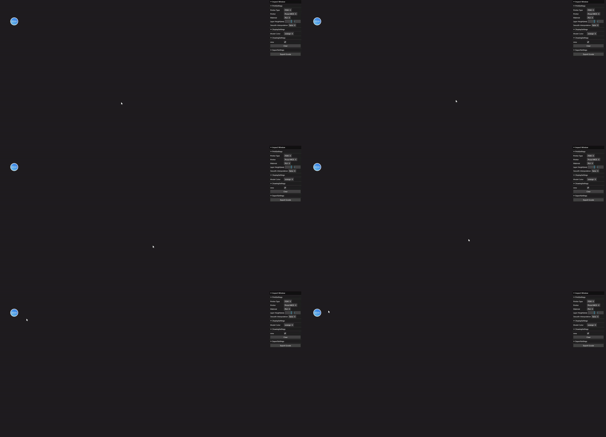
Construct a web app environment with node
[1]
Create a 3D modeling interface with THREE.js

[2]
Finding a way for drawing in 3D space
[2] Design Solution Specification:
Solving the arbitrary drawing problems
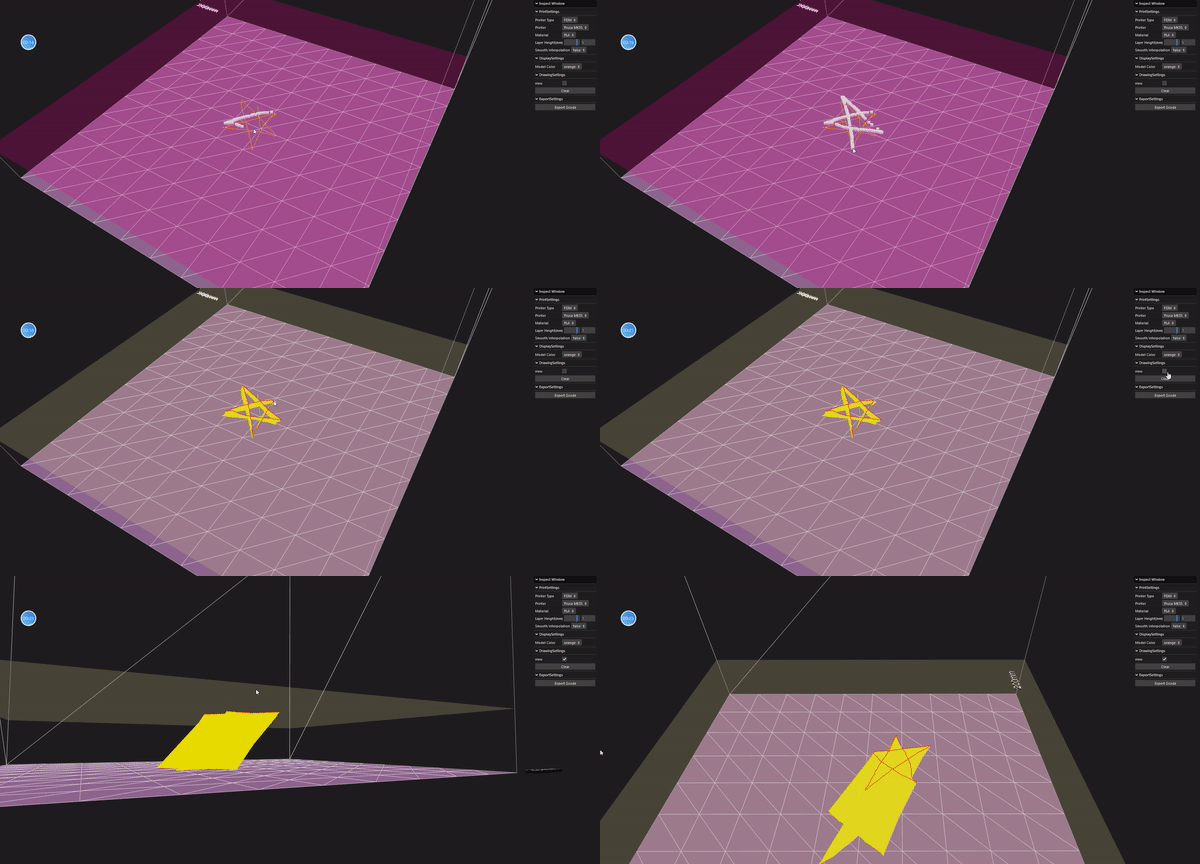
Our design solution sets surfaces as visual reference for users to perceive the relative position (depth). In the web app, there are 2 different orientation of surfaces, the users can:
1. Use the keyboard event (W, S key) to control the surface depth.
2. Use the cursor to click on the surface
3. The surface will detect the cursor by ray-casting and record the point position.
After clicking ENTER, the recorded points will construct a single line.
[3]
curve simplification
(Ramer-Douglas-Peucker Algorithm)

Because the user may draw thousands of points, to adapt the web app effeciency, we need to further simplify the line.
Fabian Hirschman
nhttps://github.com/fhirschmann/rdp/blob/master/docs/index.rst


[4]
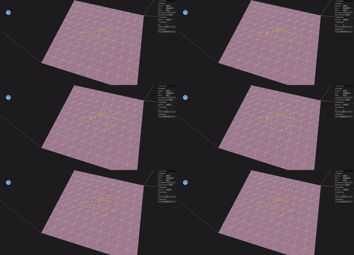
Use the arbitrary drawing as the sections of modeling
[5]
Refine Section and Generate layers
[5] Design Solution Specification:
Invalid layer recognition and geometry refinement
Because of the 3D printing machine different structure limitations, some of the layers drawed by the user are invalid to be printed. Thus we need to design a mechanical system that detects whether the drawed layer is valid based on different pinters' parameters.
Some of the validate standard:
1. The closest and farthest points of the last layer and present layer. (This is relevent to the layer thickness of the printer & filament)
2. The curve height fluctuation. (This is relevent to the shape and dimension of the printer's sprayer)
3. The layer lateral displacement.
[6]
Complete model
Export G-code


[7]
Print

Printing Experiments
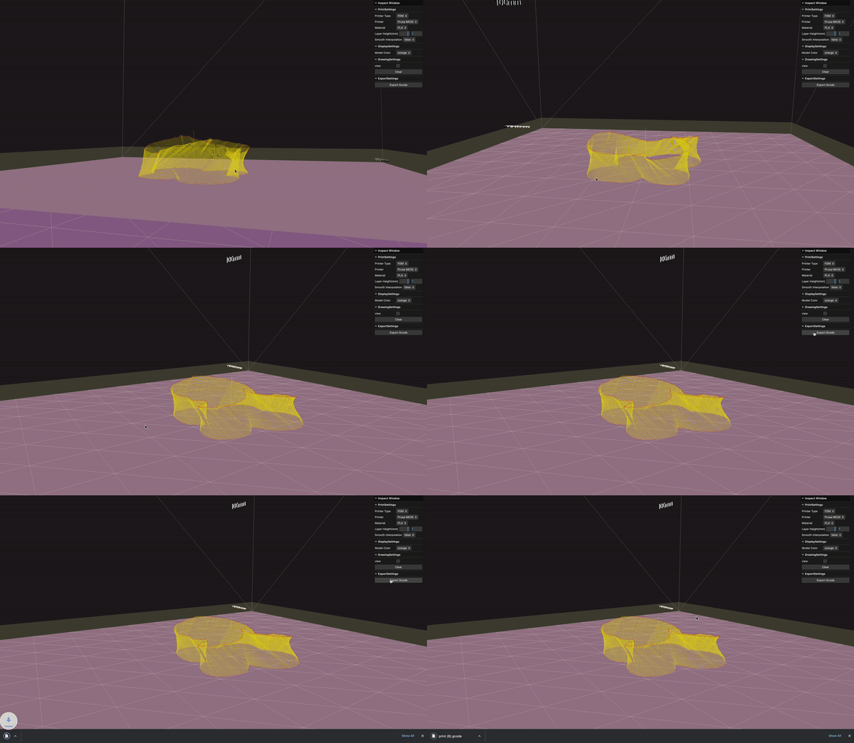

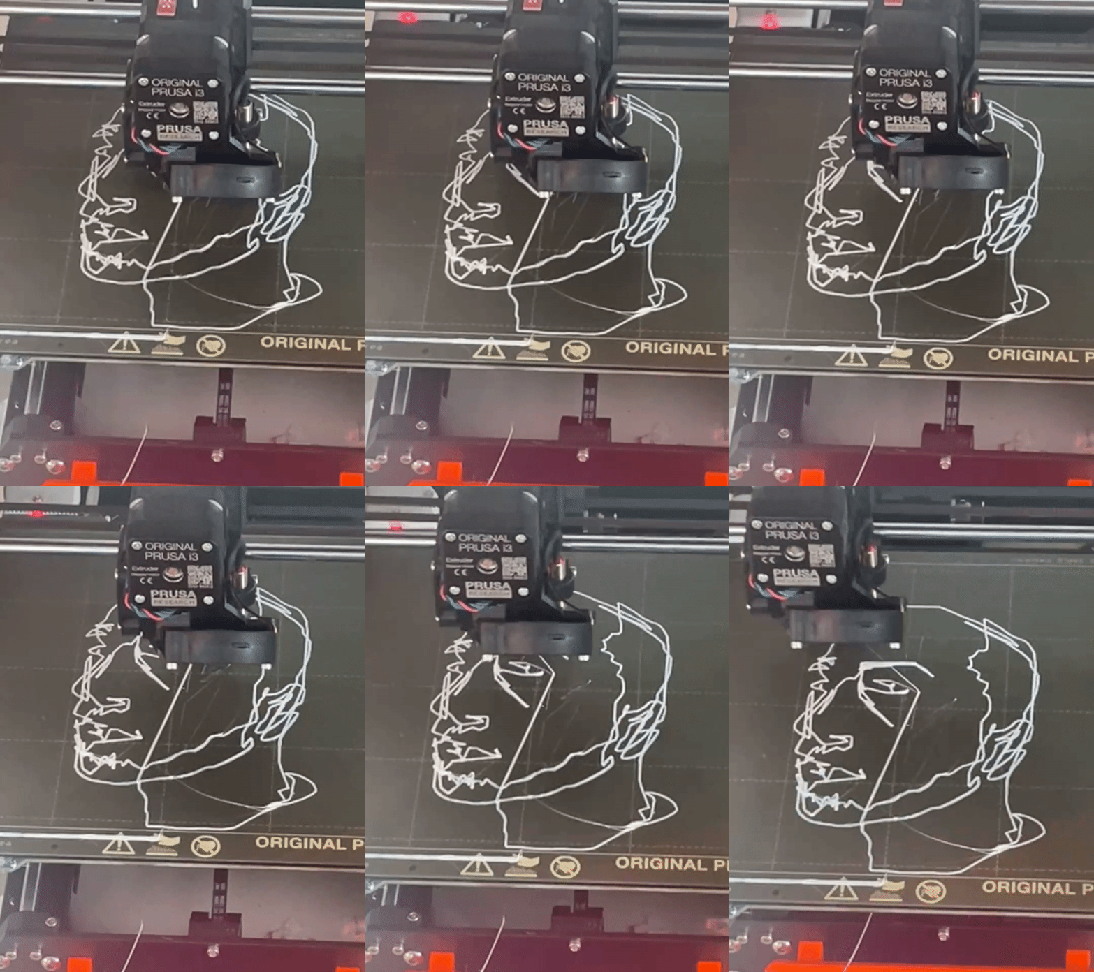

Whole process recording

Experience online
Draw to Print is now available online!
Althou some of the feature is under adjustment and construction, basic functions includes drawing, layer generating, g-code exporting are accessible.
Some operation hints:
-Click "z" on keyboard to change y or z orientation drawing surfaces
-Click "w" or "s" to move the surface
-Click on the moving surface to draw
-Click "Enter" on the keyboard to finish the line
-Press "c" in order to change perspective to view your model
-Export G-code at the right-top bar

